A3
A3 Assignment - Truss Analysis
Overview
Each individual will analyze a simple truss using the "Method of Joints". They will also perform an approximate analysis of their first Knex truss using the
Bridge Designer software. They will comment on whether the analysis provides understanding of the failure mode of their first truss design.
Details
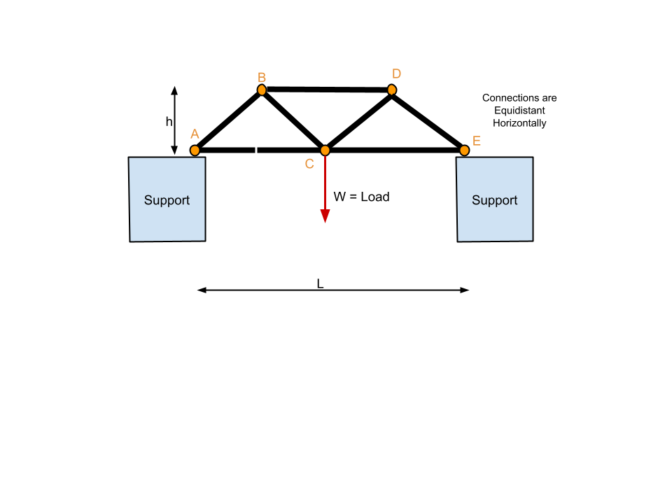
- Using the configuration shown in the drawing at the bottom calculate the forces in the truss members using the "Method of Joints" with h & W as defined in the constraints below.
- Show your calculations either in a scanned paper document or via an Excel spreadsheet (recommended)
- Using the results of the previous truss analysis create a diagram similar to the one below with the forces next to the members or in a table on the diagram with member-to-member (e.g. "C-D") labels
- Positive will mean Tension; Negative will mean compression
- Using the online Bridge Designer replicate this analysis
- Present a screen capture showing your analysis
- Define what you have to do to make the results of the hand analysis correspond to online Bridge Designer
- Hint: It involves "scaling"
- Use the online Bridge Designer to model your Knex Truss
- Present a screen capture showing your analysis
- Apply the logic of #4 above to calculate the forces in your Knex truss with an assumed load of as given in the constraints.
- Define in words how you might use this type of analysis to improve the design your bridge given the testing information about Knex Joints in this web page
Tools
- Drawing Program - Google Docs Draw is helpful - Hand drawing scanned is OK
- Calculation Tool - hand or MS Excel
- Online Bridge Designer
Constraints
- For the Method of Joints Truss Analysis - individuals will have "h" and "W" and "L" as follows
-
| Last Name Begins |
"h" |
"W" |
"L"
|
| A-H |
6" |
10 pounds |
24"
|
| I-Q |
8" |
15 pounds |
24"
|
| R-Z |
10" |
20 pounds |
36"
|
- Load for your Knex Truss - 20 pounds applied to a bottom connector at the midpoint of the truss (or as close to the midpoint as possible)
Deliverables
- Web Post as part of your Blog with the content defined above
- URL of post (not general blog) submitted to VistaBB assignment
Grading Criteria
| Criteria |
Points |
Comment |
| Grammar & Spelling |
1 |
|
| Overall Completeness |
2 |
|
| Calculation of Forces via Method of Joints (MOJ) |
3 |
|
| Labeled Diagram showing results of MOJ |
2 |
|
| Bridge Designer Image Replicating MOJ |
1 |
|
| Making Bridge Designer Correspond to MOJ |
2 |
|
| Bridge Designer Applied to Your Knex Truss |
2 |
|
| How to Use Analysis to Improve the Design of Knex Bridge |
2 |
|
| Total |
15 |
|
Truss Diagram for Joint Analysis
Can you please clarify the requirements for number 5?
ReplyDelete5)Use the online Bridge Designer to model your Knex Truss
1)Present a screen capture showing your analysis
2)Apply the logic of #4 above to calculate the forces in your Knex truss with an assumed load of as given in the constraints.
using bridge designer to construct our bridge results in the tension and compression values being unreadale due to the number of them on the screen overlapping.
If you're unable to read the the results of the analysis you have several choices:
ReplyDeletea) draw your diagram larger if possible
b) Simplify your truss in some manner so you reach the state at which the results are readable. This is acceptable because we're interested in your learning from the analysis in manner that allows you to improve your design. Hopefully you'll be able to experiment to do so.
Is it ok if we converted pounds to newtons and feet to meters to do the calculations?
ReplyDeleteSee my reply in the Post Units for Results
ReplyDeletehttp://engr103-ay113-mitchell.blogspot.com/2012/05/units-for-results.html